

Description
⚙️ Project Overview
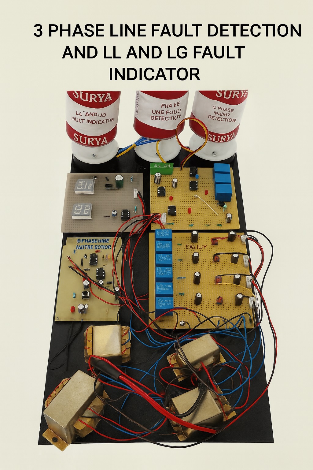
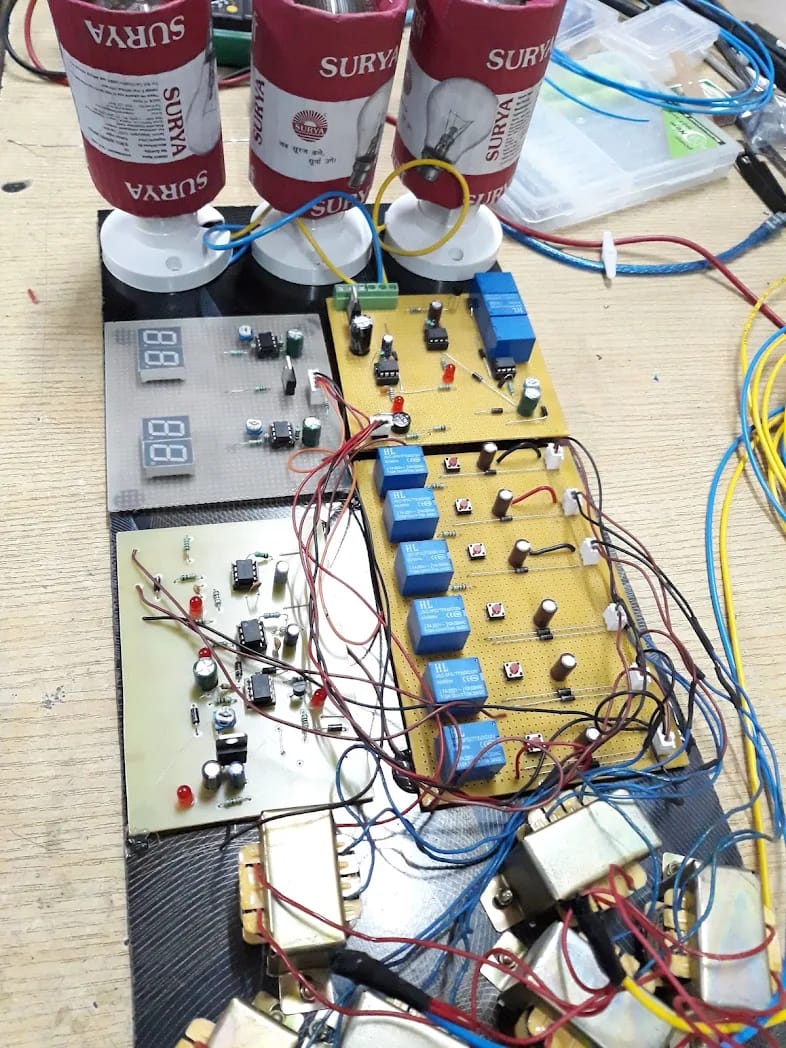
The 3-Phase Fault Detection and Indicator Project is an intelligent protection system designed to monitor and detect faults in 3-phase electrical lines.
When a fault such as Line-to-Line (LL) or Line-to-Ground (LG) occurs, the circuit instantly identifies the fault type, isolates the affected line, and displays the fault on a 7-segment display.
This system provides students with hands-on experience in fault identification, power system protection, and circuit isolation concepts — key elements in modern industrial automation and power distribution systems.
⚡ Working Principle
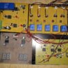
The system monitors each phase of a 3-phase supply using sensing circuits connected through resistors and relay units.
-
Normal Condition:
-
All three phases (R, Y, B) are active and the output display shows a “Normal” condition.
-
-
Line-to-Line (LL) Fault Detection:
-
When two phases (e.g., R-Y or Y-B) short due to insulation failure or accidental connection, the circuit detects overvoltage/current changes.
-
A Timer IC (555-based delay circuit) processes the fault and displays “LL” on the 7-segment display.
-
A relay simultaneously isolates the affected line.
-
-
Line-to-Ground (LG) Fault Detection:
-
When one phase contacts the ground, leakage current is detected.
-
The Timer IC triggers a signal to display “LG” on the 7-segment indicator and disconnect the faulted line.
-
-
Fault Indication and Reset:
-
LED indicators and relays identify the faulted line (R, Y, or B).
-
A manual reset switch restores the circuit to normal operation once the fault is cleared.
-
This simulation demonstrates how real-world transmission and distribution networks identify and isolate faults to protect connected equipment.
🔩 Key Features
-
Detects both Line-to-Line (LL) and Line-to-Ground (LG) faults.
-
Uses Timer IC (NE555) for delay-based detection and control.
-
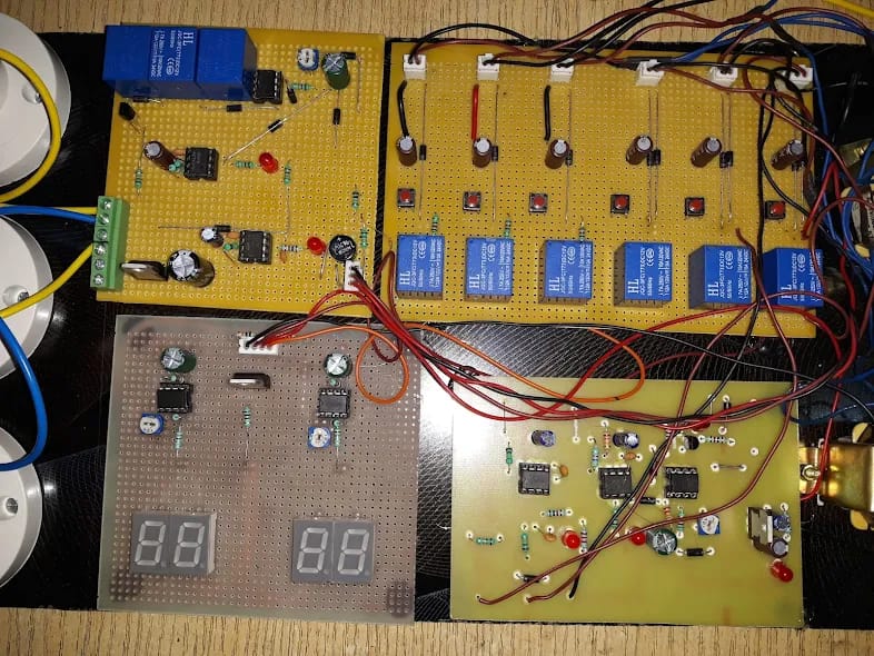
7-Segment Display shows real-time fault indication.
-
LED fault indicators highlight affected phases (R, Y, B).
-
Relay system provides line isolation during fault conditions.
-
Compact design ideal for lab demonstrations and exhibitions.
-
Fully assembled and tested kit with clear working explanation.
🧰 Technical Specifications
| Parameter | Specification |
|---|---|
| Supply Voltage | 230V AC (Stepped down to 12V DC for circuit) |
| Controller Type | Timer IC (NE555) |
| Display Type | Dual 7-Segment LED Display |
| Fault Types Detected | Line-to-Line (LL), Line-to-Ground (LG) |
| Relay Type | 12V DC, SPDT Electromechanical Relay |
| Indicators | LEDs for each phase (R, Y, B) |
| Protection Type | Automatic relay cutoff on fault detection |
| PCB Type | Multi-board assembly with relays and display interface |
| Output Display | Fault Type Displayed: LL / LG |
| Power Consumption | <10W |
| Additional Circuits | Transformer, Rectifier, Voltage Regulator |
🎓 Educational Outcomes
Students will learn:
-
Real-time 3-phase fault detection and protection techniques.
-
Operation of Timer ICs in sequential fault timing applications.
-
Relay operation and isolation mechanisms in electrical protection systems.
-
7-segment display interfacing and logic indication design.
-
Power system safety and automation fundamentals.
This project provides practical exposure to power electronics, control systems, and electrical safety concepts vital for EV charging, transmission, and industrial automation systems.
💡 Applications
-
Industrial and domestic 3-phase distribution fault protection.
-
Substation monitoring and automatic isolation.
-
Power transmission training and educational models.
-
Electrical protection system design experiments.
-
Smart grid safety demonstrations.
🧩 Advantages
-
Protects equipment from short circuits and electrical damage.
-
Identifies fault type and affected line accurately.
-
Simple, low-cost, and reliable system.
-
Easy fault indication with visual and digital display.
-
Ideal for academic demonstrations and industrial simulations.
📦 Package Includes
-
Fault Detection Main PCB with Timer ICs
-
Relay and LED Indication Board
-
Dual 7-Segment Display Board
-
Power Transformer and Regulator Board
-
Pre-wired connectors and test terminals
-
Documentation (Word + PDF)
-
Circuit and Block Diagram Images
-
User Manual and Demonstration Guide