Description
-
⚙️ Project Overview
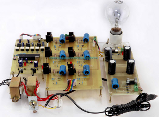
A Closed Loop 3-Phase Sine Wave Inverter is an intelligent and high-efficiency DC-to-AC conversion system that generates a stable three-phase AC output from a DC source.
Unlike conventional inverters, this system utilizes Sinusoidal Pulse Width Modulation (SPWM) to produce a near-perfect sine wave, ensuring minimal harmonic distortion (THD) and consistent voltage regulation even under load variations.
The project focuses on power conversion efficiency, waveform quality, and closed-loop feedback control, making it a key learning platform for power electronics and electric drive systems.
🔋 Working Principle
An inverter converts DC electrical energy (from a battery or DC supply) into AC power suitable for industrial and household applications.
This project operates on the Pulse Width Modulation (PWM) technique, which involves controlling the switching duration of transistors or MOSFETs to generate a smooth AC waveform.1️⃣ DC Input Source:
-
The system receives DC voltage from 12V, 24V, or 48V batteries (depending on configuration).
2️⃣ Microcontroller Control (8051 Family):
-
A microcontroller generates the SPWM signals required to trigger the MOSFETs in a 3-phase six-pulse inverter bridge.
-
The pulse width is varied based on the sinusoidal reference waveform and carrier frequency.
3️⃣ Power Conversion:
-
The inverter bridge consists of 6 MOSFET switches configured to produce 3-phase AC output (R, Y, B).
-
The SPWM control ensures smooth sinusoidal output, lower harmonic distortion, and efficient operation.
4️⃣ Closed Loop Feedback:
-
The output voltage is monitored and fed back to the controller.
-
If the load causes voltage fluctuation, the system adjusts the PWM width automatically to maintain rated voltage.
This closed-loop regulation provides better voltage stability and performance compared to open-loop inverters.
🧠 Sinusoidal Pulse Width Modulation (SPWM)
SPWM is a refined PWM technique that uses a sinusoidal reference signal compared with a high-frequency triangular carrier signal to control the output pulse width.
Benefits include:-
Reduced Total Harmonic Distortion (THD)
-
Higher output voltage utilization
-
Smooth control of speed and torque in AC motors
-
Compatibility with vector control and field-oriented drive (FOD)
🔩 Key Features
-
Converts DC power into stable 3-phase AC power (50Hz output).
-
Closed-loop voltage regulation ensures constant output.
-
SPWM control reduces harmonic distortion and enhances efficiency.
-
Microcontroller (8051) based system ensures precise switching control.
-
Can drive 0.3 HP 3-phase induction motor or 3-phase lamp load.
-
Compact, safe, and easy-to-understand educational prototype.
🧰 Technical Specifications
Parameter Specification Input Voltage 12V / 24V / 48V DC Output Voltage 230V / 440V 3-Phase AC Output Frequency 50 Hz Control Technique Sinusoidal PWM (SPWM) Controller Used 8051 Microcontroller Family Switching Devices 6x MOSFETs (Three-Phase Bridge) Protection Overload, Short Circuit, Reverse Polarity Load Options 3-Phase Induction Motor / Lamp Load Feedback Type Closed Loop Voltage Control Efficiency ~85–90% (prototype level)
🎓 Educational Outcomes
Students will gain practical exposure to:
-
Inverter design and PWM principles
-
Microcontroller-based switching control
-
SPWM generation and waveform shaping
-
Closed-loop voltage and frequency feedback control
-
Motor drive and power electronics system design
This project serves as an excellent educational tool for understanding modern inverter technology used in Electric Vehicles (EVs), UPS systems, and variable frequency drives (VFDs).
💡 Applications
-
Industrial 3-phase motor control systems
-
Renewable energy inverters (solar/wind integration)
-
Variable frequency drives (VFDs)
-
Uninterruptible Power Supply (UPS) systems
-
Electric vehicle traction inverters
-
Laboratory demonstration for power electronics
🧩 Advantages
-
Low harmonic distortion (THD)
-
Stable and regulated output voltage
-
Efficient closed-loop feedback control
-
Safe and compact design for educational use
-
Real-time waveform demonstration for lab learning
-
Compatible with advanced motor control systems
📦 Package Includes
-
8051 Microcontroller-based Control Board
-
Six-MOSFET Three-Phase Inverter Bridge
-
DC Power Supply / Battery Connectors
-
LCD Display (optional)
-
3-Phase Output Terminals
-
Motor or Lamp Load Interface
-
Documentation (Word + PDF)
-
Circuit Diagram + Block Diagram Image
-
User Manual and Test Procedure
-